- Related articles
- The difference between GBIC and CSFP
- Optical Transceivers for Cisco WS-C3750G-12S-S Switch
- Optical Transceivers for Cisco SG250-26P-K9-EU Switch
- 7 tips for choosing network card
- The Things You Need to Know about 1000BASE-LR Ethernet Standards
- All Cisco CWDM-SFP-1530's information (List price, Specs, Datasheet PDF, Compatibility mat
- Optical Transceivers for Cisco WS-C3750V2-24PS-E Switch
- Optical Transceivers for Cisco N9K-X9464TX= Switch
- Optical Transceivers for Cisco WS-CBS3130X-S Switch
- Apply to 1000BASE-LHB Standard Optical Transceiver Models

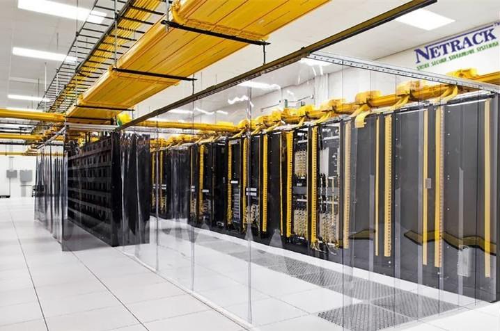
In the server rooms, we can see the huge rack cabinets everywhere; in fact, they are not only the role of the cabinet. Many cabinets will be equipped with USP power supply not only to play the auxiliary role to protect the system but to solve problems of high-density heat radiation, the management of a large number of cables, large-capacity distribution and full compatibility with different manufacturers rack-mounted equipment in the computer application. The cabinet’s features are more and more powerful. Here we talk about how to organize the cabinet. Here are two steps:
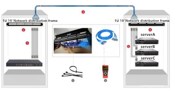
1. Notify that the user sorts out the cabinet without affecting the normal work of the user. And then according to the network topology, the existing equipment, the number of users, user groups and other factors, outline the wiring diagram and equipment location figures inside the cabinet. Then prepare the required materials: network jumper, label paper, various types of plastic cable ties.
A: start to install the cabinet: first, use screws and nuts with the random frame to fix the fixed frame; second, put the cabinet down, and install the movable wheel; third, according to the location of the device, adjust and add baffles on the fixed frame.
B: sort out the cables on the cabinet: divide the cables into groups, which are usually less than or equal to the number of wire frame behind the cabinet. Bind the power cords of all the equipment together, insert the plug from the rear access hole, and search for the respective equipment through a separate wire frame.
C: fix the device in the frame: adjust the baffle in the cabinet to the right position so that the administrator can see the operation of all the equipment without opening the cabinet door, and add baffle appropriately according to the number and size of the device. Be careful to leave a gap between the baffles. Put all the switching equipment and routing equipment used in the cabinet according to the pre-painted drawings.
D: label the cable for easy identification: after all the cables are connected, they need to be identified by the network cable, and the ready-made stickers will be wrapped around the network cable and marked with a pen (usually indicate the room number or for what purpose), require identification to be easy to understand. The crossover cable can be distinguished from the general network cable by using the sticky note with different colors. If there are many devices, the devices will be classified, numbered and labeled.
2. When everything is ready and checked correctly, then turn on the power, and make tests on the network connectivity to ensure that users work properly - this is the most important. Finally, after the arrangement, need to make document update on the contents arranged by the cabinet. Re-paint equipment layout and network cable connection figures. In the figures, indicate the equipment number and network cable identification for inspection, repair, and reference.


