- Related articles
- All Cisco CWDM-SFP-1310's information (List price, Specs, Compatibility matrix)
- Optical Transceivers for Cisco WS-C3750G-48TS-S Switch
- How do they differ? PCI vs PCI-E vs AGP
- Optical Transceivers for Cisco SG300-52P-K9-EU Switch
- The Difference between CSFP and X2
- Types of network interface card
- All Cisco ONS-SE-GE-BXD's information (List price, Specs, Datasheet PDF, Compatibility mat
- Optical Transceivers for Cisco SG250-26P-K9-UK Switch
- What is Mini GBIC?
- Optical Transceivers for Cisco ESW-540-8P-K9 Switch

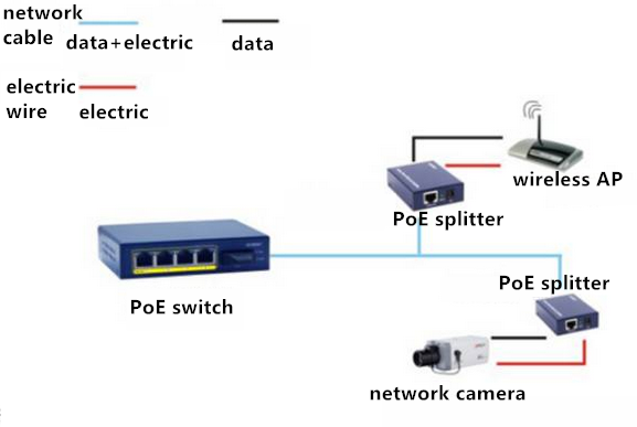
1. Switch and terminal's support for PoE
In this method, PoE switches connect wireless AP and network cameras which support PoE power directly through the network cable. This method is the simplest, but is needed to pay attention to the following two points:
1). Determine whether the PoE switch and the wireless AP or network camera are standard PoE devices.
2). Carefully confirm the purchased network cable specifications. The quality of the cable is critical. The cable of poor quality will cause that AP or IPC cannot receive power or continue to restart.
2. PoE supported by switch but not by terminal
In this method, PoE switch is connected to PoE splitter which separates the power supply into data signals and power. It has two output lines, one is the power output line and the other is network data signal output line, that is, the ordinary network line. Power output 5V / 9 / 12V, etc. can match a variety of DC input non-PoE power receiving terminal and support IEEE 802.3af / 802.3at standard. Data signal output line or the ordinary network line can be just directly connected to the network port of non-PoE power terminal.
3. No support for PoE by switch but support for PoE by terminal
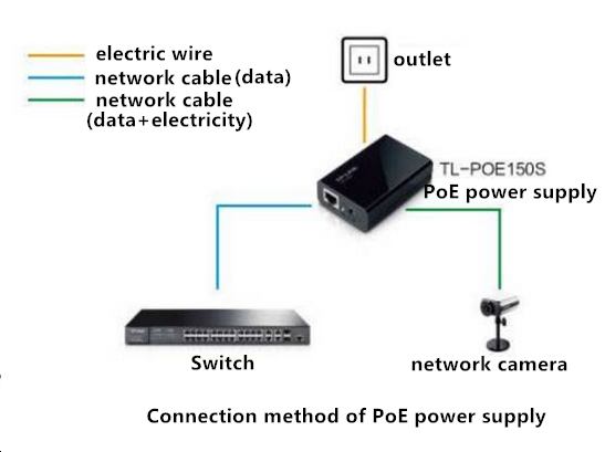
In this method, switch connects PoE power supplying power to the network cable and transmitting it to the terminal, which is conducive to the expansion of the original cabling network without any influence in the original network.
4. No support for PoE by both switch and terminal
In this program, the switch connects the PoE supplier, then the PoE splitter, and finally transmits to the terminal. Scenario 3 and Scenario 4 are suitable for the transformation of the traditional network, that is, the original switch does not support PoE power supply, but wants to take advantages of PoE power supply.
AS for the practical use, how to connect network line?
1). If your POE switch, POE power supply module are standard PSE devices, then the network line connected to the wireless AP or IPC casually will not burn. In the standard POE power supply process, there is a detection process, which will ensure that no standard equipment is powered. How to distinguish between standard equipment and non-standard equipment, you can see how to distinguish between standard POE power supply and non-standard POE power supply.
2). If your PSE equipment is strong for the type, then the wiring must be very carefully before the instructions, see the power supply PIN pin is 1 2 3 6 or 4 5 7 8, if there is no manual, you can also use a multimeter to detect, if there is Stable 12V / 24 / 48V output is the power supply feet. Find out the power supply PIN pin, cannot directly access terminal equipment. The other end of the wireless AP or IPC to figure out how much input voltage, network port circuit has been modified, if not modified, then it is likely to be connected after the network port burned. If the circuit is not modified need to use POE separator.
Upon understanding the above two points, you will be confident in the engineering applications in the wiring before the connection. As now on the market there is a lot of non-standard equipment, you must be very careful before wiring.


