- Related articles
- Optical Transceivers for Cisco WS-C3560E-12SD-E Switch
- The difference between SFP and QSFP+
- All Cisco GLC-TE's information (List price, Specs, Datasheet PDF, Compatibility matrix)
- All Cisco CFP-40G-LR4's information (Overview, List price, Specs, Datasheet PDF, Compatibi
- How do they differ? PCI vs PCI-E vs AGP
- All Cisco XFP-10GER-OC192IR's information (List price, Specs, Datasheet PDF, Compatibility
- All Cisco QSFP-4X10G-LR-S's information (Overview, List price, Specs, Datasheet PDF, Compa
- Optical Transceivers for Cisco WS-C2960CG-8TC-L Switch
- All Cisco DS-X2-FC10G-SR's information (List price, Specs, Datasheet PDF, Compatibility ma
- All Cisco DWDM-XFP-54.13's information (List price, Specs, Datasheet PDF, Compatibility ma


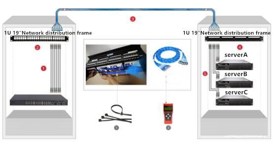
MPO (Multi-fiber Push On) is a kind of MT connector series. The compact design of MPO makes its numerous cores and small size. MPO connector is widely used as the interior connection applications of FTTX, 40/100G SFP, SFP+ and other transceivers in the high-density integrated fiber circuit needed in the process of cabling. The main products of MPO include MPO fiber patch cable, MPO fiber adapter, MPO spare parts, MPO core insert, MPO distributing box, MPO connector, and MPO fiber cable.
At present, high-density MPO/MTP fiber pre-connection system is mainly applied in three major areas: the high-density environment of the data center, fiber to the building, optical splitter, and interior connection of 40G, 100G SFP, and SFP plus light transceiver
1. What is the polarity of MPO products?
The match from transmitter(Tx) to receiver(Rx)in the two ends of fiber link is called polarity. MPO products have 3 kinds of polarities: (positive polarity) type A, (flip line for correct polarity) type B and (cross polarity) type C.
1) Positive polarity: In type-A MPO-MPO patch, the positions of fiber cores at the two terminals are same. The locating key on the one end points up while the one on the other end points down.

2) Polarity correction by turning line pair: In type-B MPO-MPO patch, the positions of fiber cores at the two ends are opposite. Fiber core 1 of one end is at position 12 on the other end. The locating keys of both ends are in the same direction.

3) Cross polarity: In type-C MPO-MPO patch, the positions of contiguous fiber cores are cross. Fiber core 1 of one end is at position 2 on the other end while fiber core 2 of one end is at position 1 on the other end. The locating key on the one end points up while the one on the other end points down.

2. How to manage the polarity?
Three polarity methods provisioned by the TIA568 standard are respectively called type A, type B, and type C. To reach the TIA568 standard, MPO trunk fiber cables are also divided into the shoot-through cross, complete cross and line pair crosses.
1) Method A: A module with through wiring and two different patches are adopted. The patch of one end is through line pair while that of the other end is reversal line pair. The following picture (Rx represents receiving and Tx means transmitting) shows the connectivity method-A using the through MPO trunk fiber cable. To ensure the accuracy of polarity, the standard and duplex A-to-B patch are used in the left fiber link while the A-to-A patch is employed in the right fiber link.

2) Method-B: A module with through wiring and a patch with through line pair are adopted. The following picture shows the connectivity method-B using the complete cross MPO trunk fiber cable. Due to the opposite corresponding positions of fiber at the ends of the MPO trunk fiber cable, the standard A-to-B patch is employed at the ends of the fiber link.

3) Method-C: In the trunk fiber cable, line pair is turned to correct the polarity using the interconnected module and same patch. The following picture shows the connectivity method-C where MPO trunk fiber cable with cross line pair is used and the standard A-to-B patch is employed at the ends of the fiber link.

3. How to test the polarity?
The correctness of 8 or 12 even 24 fibers can be tested through the polarity tester which detects the fault of the single fiber in the MPO system.