- Related articles
- Optical Transceivers for Cisco WS-C3560E-24TD-SD Switch
- Optical Transceivers for Cisco WS-C2960-24PC-S Switch
- What is the speed of Gigabit Ethernet?
- All Cisco GLC-FE-100BX-U's information (List price, Specs, Datasheet PDF, Compatibility ma
- What Is GYTZA Fiber Optic Cable?
- All Cisco SFP-OC12-MM's information (List price, Specs, Datasheet PDF, Compatibility matri
- All Cisco SFP-10GB-LR's information (List price, Specs, Datasheet PDF, Compatibility matri
- The difference between DWDM and WDM
- All Cisco ONS-SI-GE-LX's information (List price, Specs, Datasheet PDF, Compatibility matr
- All Cisco ONS-SE-GE-BXD's information (List price, Specs, Datasheet PDF, Compatibility mat

Introduction
Fiber Optic Cable is associated with numerous technical specification or characteristics. In fact, many users are attracted to purchase a particular Fiber Optic Cables by its technical specifications. Therefore, it is critical to understand some of the specification of various fiber optic cables.
General specifications
This section details the requirements for 8 to 24 fiber aerial cables for use on Trunk and Junction routes. The cables shall comply with the requirements as indicated in the ETS for single mode optical fiber cables to be used in aerial applications as in accordance with the existing I-ETS 300 229 recommendations. All the fibers offered for all cable applications shall be of the same type and origin. Additionally, there shall be no fiber splice in a delivery length. Additionally, the characteristics of the Optic Fibre cables shall be in accordance with ITU-G Rec. G.652D (Low Water Peak Fibre)., IEC 793 and IEC 794. The following additional requirements shall also apply. 2.
Cable Constructions
Strength Member The aerial placement cables shall be a figure of 8 type in cross section, having an integrated steel messenger wire. The cable shall be designed with sufficient strength members to meet installation and service conditions so that the fibers are not subject to excessive strain. The cable shall be designed for span lengths of up to 70m.
Colour Coding
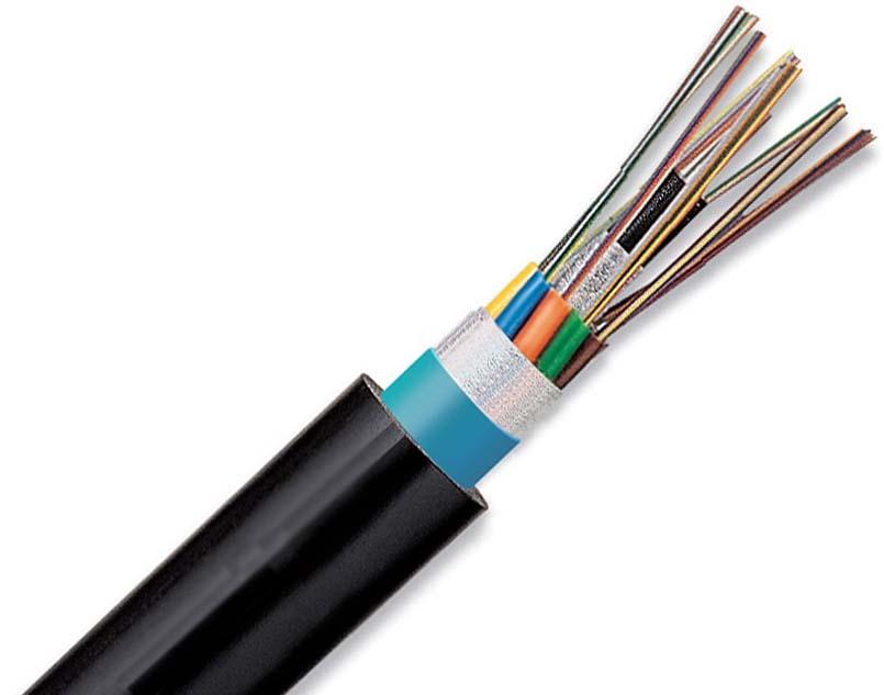
Loose tubes shall be individually colored for ease of identification. Individual fibers shall also be color coded. The method used for coloring and tubing fibres shall be fully described
Cable Sheath Layers
The cable core shall be covered with a seamless black sheath mask of U.V. stabilized weather resistant polyethylene. The outer sheath shall have a minimum thickness of 1mm. The cable sheath shall be printed in yellow with a suitable legend to be agreed between the Contractor and the SALCAB Project Manager. The sheathing method including control measurements shall be fully described. In particular, the cable diameter measurement, high voltage testing, printing and take-up on drum shall be described.
Loose Tube Protection
The cables shall be of the loose tube, slotted core or Ribbon type of construction. The material used e.g.
PBT and the tubing process shall be fully described.
Loose tube type cables shall have 2, 4, 8 or 12 fibers per tube.
For slotted core type cables, Tenderers shall state the number of fibers per slot.
The interstices of the cable core shall be filled with a water repellent compound and the core covered with a plastic wrap.
Slotted core cables shall have the slots filled with a thixotropic jelly.
Stranding
The tubes shall be wrapped around a non-metallic central strength member. The stranding method shall be fully described. Either helical or SZ stranding may be offered.
Target Diagram
Tenderers shall submit a target diagram for each type and size of cable offered. The target diagram shall contain the coding information used to identify the individual cable elements.
Conclusion
The Fiber Optic Cables are given its identity by the technical specification. Many companies are enquiring the technical properties of a Fiber Optic Cable before doing the purchase something which is good. The technicians are also advising the users to research on the technical properties of the fiber optic cable before doing the purchase.


