- Related articles
- All Cisco SFP-10G-ER-S's information (List price, Specs, Datasheet PDF, Compatibility matr
- What is 10GBASE-T transceiver?
- Applicable to 1000BASE-ZX Standard Optical Transceiver Models
- How to install NIC card?
- Optical Transceivers for Cisco WS-C2960XR24TDI-RF Switch
- Optical Transceivers for Cisco WS-C2960+24PC-L Switch
- All Cisco DS-X2-E10G-SR's information (List price, Specs, Datasheet PDF, Compatibility mat
- Applicable to 1000BASE-EX Standard Optical Transceiver Models
- How Much Do You Know About Types of Fiber Optic Cables?
- Applicable to 10GBASE-LRL Standard Optical Transceiver Models

PCI Express (Peripheral Component Interconnect Express), officially abbreviated as PCIe, is a high-speed serial computer expansion bus standard, designed to replace the older PCI, PCI-X, and AGP bus standards. PCIe has numerous improvements over the older standards, including higher maximum system bus throughput, lower I/O pin count and smaller physical footprint, better performance scaling for bus devices, a more detailed error detection and reporting mechanism (Advanced Error Reporting, AER), and native hot-plug functionality. More recent revisions of the PCIe standard provide hardware support for I/O virtualization.
The PCI Express electrical interface is also used in a variety of other standards, most notably in ExpressCard as a laptop expansion card interface, and in SATA Express as a computer storage interface.
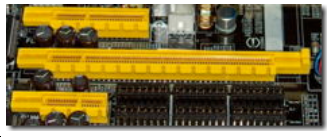
PCIE Slots
The PCI Express specification allows slots to have different physical sizes, depending on the number of lanes connected to the slot. See Figure 5. This allows reducing the size of the space needed on the motherboard. For example, if a slot with an x1 connection is required, the motherboard manufacturer can use a smaller slot, saving space on the motherboard.
However, bigger slots can actually have fewer lanes than the diagram shown in Figure 5. For example, many motherboards have x16 slots that are connected to x8, x4, or even x1 lanes. With bigger slots it is important to know if their physical sizes really correspond to their speeds. Moreover, some slots may downgrade their speeds when their lanes are shared. The most common scenario is on motherboards with two or more x16 slots. With several motherboards, there are only 16 lanes connecting the first two x16 slots to the PCI Express controller. This means that when you install a single video card, it will have the x16 bandwidth available, but when two video cards are installed, each video card will have x8 bandwidth each.
How to Remove PCIE Slot Cover
It's not difficult at all difficult to remove the slot cover. You just need to lay the computer down on its side, and you should be able to unscrew them from the back of the case - same place as where the top of the card screws in.
Occasionally you'll find a case with an access panel covering the screws, but once you remove that, same thing.
The screws are always in the same place; only thing that tends to be different is whether you access them from the inside of the case with the side cover off, or once in a while from the outside of the case with a separate cover over them.
Summary
A little-known fact is that you can install any PCI Express expansion card in any PCI Express slot. For example, you can install an x1 expansion card in any kind of PCI Express slot; it doesn’t need to be installed in an x1 slot. So, if you have an x4 expansion card but your motherboard doesn’t have an x4 PCI Express slot, no problem; simply install it in an x8 or x16 slot.


