


- Related articles
- All Cisco DS-SFP-FC-2G-SW's information (List price, Specs, Datasheet PDF, Compatibility m
- Optical Transceivers for Cisco ME-3400-24TS-A Switch
- Used in 1000BASE-CWDM Standard Optical Transceiver Models
- Optical Transceivers for Cisco SG500XG-8F8T-K9-G5 Switch
- Optical Transceivers for Cisco WS-C3560CX-8XPD-S Switch
- How to check NIC card?
- How to Test a Fiber Optic Transceiver?
- Easiest Way to Know the History of Fiber Optic Cable
- Optical Transceivers for Cisco SLM248PT-G5 Switch
- Optical Transceivers for Cisco WS-C2960X-48LPS-L Switch


In fiber-optic networks, optical fiber detection plays an important role both in the installation of new fiber and overhaul of older optical fibers. It is well known that optical power meters are used to measure optical power and detect the light loss. This article will focus on the use of optical power meter and purchase.
Optical power
In simple terms, the optical power is the "brightness" or "intensity" of the light. In the fiber network, the unit of the optical power is usually expressed in milliwatts (mw) and decibels (dBm), where the relationship is: 1mw = 0dbm, that is, 2mw = 3dbm, it should be noted that less than 1mw decibel milli is negative.
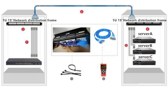
Test the power with an optical power meter

Open the network optical device, just use an optical power meter and an optical fiber connector adapter can measure the transmitter or receiver power.
Before measuring power, the wavelength and other parameters of the optical power meter must be set within the specified range. After everything is ready, the optical power meter can be connected to the transceiver side, the receiver's power can be measured, or it can be connected To the light source, measure the power of the transmitter; Finally, write down the measured value, compare it with the power value specified by the device to see if it is within the specified floating range.
In addition to measuring the optical power, the optical power meter can also be used with the light source to measure the optical loss.
How do I test the fiber loss with an optical power meter and a light source?

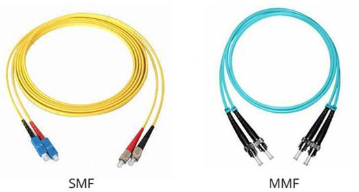
Optical fiber loss is the light from the transmitter to the fiber when the power and light to the receiver when the power difference, to measure fiber loss, not only the need for the optical power meter, also need light. In general, the measurement of multi-mode fiber loss, the need to use 850 / 1300nm LED light source, and measurement of single-mode fiber loss, the need to use 1310 / 1550nm laser light source. In addition, in order to accurately measure fiber loss, it is necessary to make the test environment and conditions of the fiber and connector similar to the actual working conditions, that is, select the appropriate light source and fiber optic cable, and the cable has a standard transmit power, the power of the light source without any influences.
At present, there are two main ways to measure fiber loss: one end loss measurement method and two end loss measurement method. Single-ended loss measurement method only uses the transmission cable, and the double-end loss measurement method in addition to using the transmission cable, the power meter is connected to a receiving cable. The single-ended loss measurement measures the losses generated by the connection of the connector to the transmit cable and the losses generated in the fiber, connector, or other connectors. As a result, each connector can be tested separately, the best way to measure fiber jumpers; the double-ended loss measurement measures the losses between the two connectors and all the fibers, including the loss between the connector and the connector. The following figure shows the specific information of the two measurement methods, in which the left side of the single-ended loss measurement method, the right side of the double-ended loss measurement method.

Optical power meter purchase guide
An optical power meter is a useful tool for optical fiber measurement applications such as optical power measurement and fiber loss measurement. Due to the specific application of the user, it is necessary to select the appropriate optical power meter:
1. Select the optimal probe type and interface type
2. Evaluate calibration accuracy and manufacturing calibration procedures to match your fiber and connector requirements
3. Make sure that the model of the optical power meter is the same as the desired measurement range and display resolution
4. Have the function of measuring the direct insertion loss (dB)
Common fiber optic test applications
-
Measuring the absolute power in a fiber optic signal. For this application, the power meter needs to be properly calibrated at the wavelength being tested, and set to this wavelength.
-
Measuring the optical loss in a fiber, in combination with a suitable stable light source. Since this is a relative test, accurate calibration is not a particular requirement, unless two or more meters are being used due to distance issues. If a more complex two-way loss test is performed, then power meter calibration can be ignored, even when two meters are used.
-
Some instruments are equipped for optical test tone detection, to assist in quick cable continuity testing. Standard test tones are usually 270 Hz, 1 kHz, 2 kHz. Some units can also determine one of 12 tones,[1]for ribbon fiber continuity testing.
Test automation
Typical test automation features usually apply to loss testing applications, and include:
-
The ability to set the unit to read 0 dB at a reference power level, typically the test source.
-
The ability to store readings into internal memory, for subsequent recall and download to a computer.
-
The ability to synchronize the wavelength with a test source, so that the meter sets to the source wavelength. This requires a specifically matched source. The simplest way of achieving this, is by recognizing a test tone, but the best way is by transfer of data. The data method has benefits that the source can send additional useful data such as nominal source power level, serial number etc.
Wavelength-selective meters
An increasingly common special-purpose OPM, commonly called a "PON Power Meter" is designed to hook into a live PON (Passive Optical Network) circuit, and simultaneously test the optical power in different directions and wavelengths. This unit is essentially a triple power meter, with a collection of wavelength filters and optical couplers. Proper calibration is complicated by the varying duty cycle of the measured optical signals. It may have a simple pass/ fail display, to facilitate easy use by operators with little expertise.
Wavelength sensitivity of fiber optic power meter is a problem when using a photodiode for voltage current measurement. If the temperature-sensitive measurement replaces voltage-current measurement by photodiode the wavelength sensitivity of an OPM can be reduced. Thus if the photodiode is reverse biased by a constant voltage source and supplied with constant current, when triggered by light the junction dissipates power. The temperature of the junction rises and the temperature rise measured by thermistor is directly proportional to the Optical power. Due to constant current supply, the reflection of power to photodiode is nearly zero and the transition to and fro of electrons between valence band and conduction band is stable.
How to Use an Optical Power Meter?
An optical power meter displays two key test parameters that allow fiber design specifications like insertion loss or low attenuation to be evaluated. The first is the wavelength setting in nanometers (nm) and the second is the power level in deciBels(dB or dBm). Optical loss is measured in dB, a dimensionless unit which is a ratio of the measured value to a reference value. Power measurement can be displayed using dBm as the unit of measure at a specific resolution. The dBm unit quantifies the power level based on a reference value of 1 milliwatt for 0 dBm.
The versatility of an optical power meter allows it to be utilized for other basic fiber testing functions such as continuity testing. Establishing the presence of signal across a fiber is important for quick fiber link verification in the field with minimal equipment changes. When deployed as part of an optical loss test set, an optical light meter reading can also be used to conveniently ascertain fiber length and send/receive polarity.