- Related articles
- All Cisco DS-SFP-GE-T's information (List price, Specs, Datasheet PDF, Compatibility matri
- The Difference between Dedicated and Integrated Network Card
- All Cisco XENPAK-10GB-ZR's information (List price, Specs, Datasheet PDF, Compatibility ma
- Optical Transceivers for Cisco SG500-28P-K9-G5 Switch
- Optical Transceivers for Cisco N9K-X9636PQ= Switch
- About Transceiver & Cisco Transceiver Modules
- The New Easy-to-Use Managed Switches-Cisco 350 Series
- Applicable to 1000BASE-T Standard optical transceiver models
- All Cisco QSFP-40G-SR4’s Information (Overview, Features, Datasheet PDF, Price, Specificat
- Optical Transceivers for Cisco N5K-C5548UP-DEMO Switch

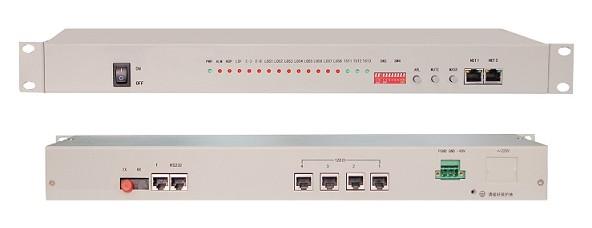
With the development of the monitoring industry, optical video converter began to play an increasingly important role in the safe city, highway, urban intelligent transportation, urban rail transit and other fields. So, in the use of optical at the same time, what do you need to notice when using the optical video converter?
Correctly select the power supply and installation environment of the optical video converter
Video converter is divided into two parts of the transmitter and receiver, (so some people called it “optical transmitter and receiver”), because the transmitter is generally installed with the front video capture device, so the installation location to be relatively dispersed, and to be equipped with an independent chassis to its power supply. There are two main types of power supply, one is the central power supply, and the other is the local power supply. As the installation of the transmitter is relatively scattered, so the use of centralized power supply is unlikely. But the receiver is generally installed in the monitoring center of the machine room, if the same machine and the use of chassis power supply, then will occupy part of the room space, and will appear messy, cannot be unified management. Therefore, the receiver power supply generally use the card-type chassis power supply, but you cannot put the slot full, every few slots empty one, is conducive to heat machine cooling. (Note: The laser module and the photoelectric conversion module of the optical transceiver avoid the impact of the instantaneous pulse current, so it is not necessary to switch the switch frequently.
Optical transmitter laser components are the core of the device; the working conditions have a higher demand. Many manufacturers in order to ensure that equipment can work properly, equipment are generally equipped with refrigeration, exhaust system. If the ambient temperature exceeds the approved temperature range, the device will not work properly. Therefore, in the hot summer season, especially in the central room heating equipment, ventilation and cooling conditions and poor place, good installation of air conditioning system to ensure the normal work of the optical transmitter and receiver. In addition to ensuring the heat, the use of optical in the process but also does a good job of moisture, water, dust and other safety measures, so that the optical function of normal work.
Pay attention to lightning protection measures
Optical transmitter part is generally installed in the outdoor equipment box because the summer is often accompanied by thunderstorms, so do light mine work is particularly important lightning protection, lightning protection measures are good or bad directly related to the optical the probability of failure. As long as good preventive measures, you can help reduce the probability of failure of the optical transceiver.
1. Do the grounding device, because the current through the grounding device into the earth, the basic will not have a devastating impact on the equipment.
2. Front-end equipment to install surge protector.
3. Data mine and power lightning protection devices such as lightning protection device is also essential to install the lightning protection device must make lightning protection close to the access port, if the lightning device interval video port, the data port too far is to carry forward the lightning protection effect.
Correctly debug optical video converter
Optical debugging is mainly for optical fiber and data channel debugging. As the optical transceiver is divided into many types, so in the actual environment debugging optical transceiver is sure to follow the instructions on the data dial and interface definition to debug data wiring. Of course, many users in the debugging process there will be debugging the unreasonable situation. The reason for this phenomenon is not necessarily the optical transmitter and receiver failure, there may be other causes. We can investigate the following aspects:
1. The fiber itself has not been tested, the optical path is unreasonable or unstable or the light attenuation is too large;
2. Front-end equipment failure, such as the camera has no video or no power;
3. Back-end equipment failure, such as the monitor without video, keyboard control protocol is wrong, cannot control itself;
4. Connection line failure, such as the video head of the welding is wrong, the control line is wrong, or the connection line plugged wrong, then reverse and so on.
Daily maintenance
The general working environment of optical is very bad, which requires us to pay attention to the daily life of the maintenance of optical transmitter and receiver. Generally, in the use of a period of time, the fiber will appear at the mouth of dust or debris, likely to cause infarction, thus affecting the normal transmission of video and data. At this time we can use industrial anhydrous alcohol and clean paper to clean the fiber head, to avoid adhesion of dust. In addition, the room cleanliness should also be maintained, to avoid dust into the fiber port.


