- Related articles
- Optical Transceivers for Cisco WS-C3650-24PWD-S Switch
- How to Replace Network Card in Laptop?
- Optical Transceivers for Cisco IE-2000-8TC-G-N Switch
- Optical Transceivers for Cisco WS-C2960XR-24PD-I Switch
- All Cisco SFP-10G-ER-S's information (List price, Specs, Datasheet PDF, Compatibility matr
- All Cisco X2-10GB-LR’s Information ( Overview, Datasheet PDF, Features, Price, Specificati
- What Is Quad Port Network Card?
- Analysis on the performance of common external wireless network card and purchasing skills
- Optical Transceivers for Cisco ME-3400E-24TS-M Switch
- All Cisco ONS-SC+-10G-ER's information (List price, Specs, Datasheet PDF, Compatibility ma

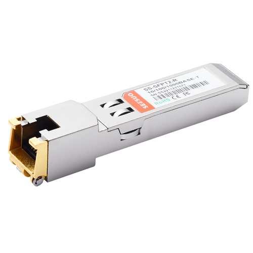
The optical module integrates precise optical elements and circuit elements. In the daily use, operation by specification should be noticed; otherwise, the optical module is easily broken. Do you know that there is SFP electrical port module in SFP optical module? How to install and remove SFP electrical port module? The article will give a detailed introduction to the specification of SFP electrical port module's installation and removal.
1. Introduction to SFP Electrical Port Module
One terminal of SFP RJ-45 module is SFP gold finger connected with the main engine, and the other terminal is common LC interface connected with the optical patch. But sometimes live environment requires using RJ45 interface to connect with a copper network cable. But Internet interface of the device is not enough. Then SFP interface must be transited toRJ45 interface. The former is such an application that one terminal is SPF gold finger and the other terminal is an RJ45 interface with the general speed rate of Giga, and 10/100/1000M self-adaption.
2. Installation Specifications for SFP Electrical Port Module
1). Connecting to the terminal of interchange
Step 1: wearing antistatic gloves to prevent from static ruin.
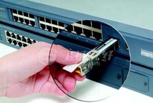
Step 2: taking SFP electrical port module out and making sure that pull-tab and label point upward, and gold finger points down. Pay attention to the notice that the obverse and reverse cannot reverse.
Step 3: the module must be inserted into the end with great efforts. When you hear "pa" or feel a slight shock, it indicates that module card is in place. When the optical module card is not in its place, the gold finger will slightly touch the single board, making the link connection possible. But under the situation of shock and collision, the optical module will have instant disconnection or even looseness and other faults.
2). Connecting to the terminal of copper network cable
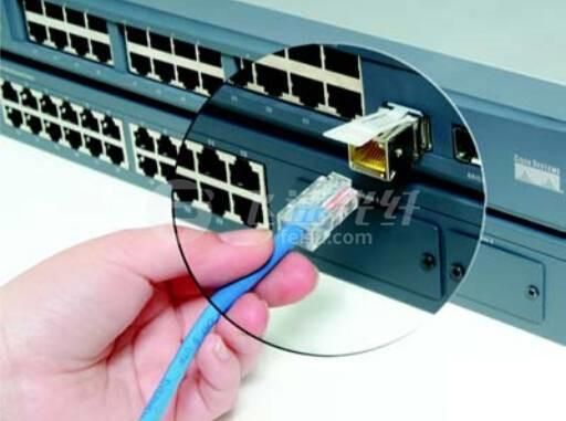
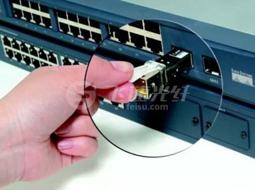
Step 1: copper network cable (generally Cat 5e ) should be inserted into the RJ-45 interface of SFP electrical port with requirements of slight actions and insertion right into the optical interface. The way of hard insertion or in sideways may damage the optical module.
Step 2: Copper cable is sure to have been inserted firmly.
3. Removal specifications for SFP Electrical Port Module
Step 1: wearing antistatic gloves to prevent from static ruin;
Step2: disconnecting copper network cable and SFP electrical port module;
Step3: putting down the lock catch of SFP electrical port module, pulling the handle and light port to about 90 degrees and slowly pulling out. Pulling out too hard or pulling out if the handle is not in place may cause damage to light module shield.
Step 4: taking dust cap to cover the optical interface of SFP port module, preventing the optical interface from long exposure and damage.
4. Attentions
1). If unnecessary, do not extract or insert SFP electrical port module, otherwise, module's using lifespan may reduce.
2). When you use SFP electrical port module, do not look steadily at two optical holes with your eyes and avoid damage to your eyes from laser's light.


