- Related articles
- Optical Transceivers for Cisco WS-C4948E-F-E Switch
- All Cisco SFP-OC12-IR1's information (List price, Specs, Datasheet PDF, Compatibility matr
- All Cisco DS-X2-FC10G-ER's information (Specs, Datasheet PDF, Compatibility matrix)
- All Cisco GLC-FE-100EX's information (List price, Specs, Datasheet PDF, Compatibility matr
- Cisco GBIC Product Line Application
- Optical Transceivers for Cisco WS-C3650-48TS-L Switch
- What is WDM transceiver?
- Optical Transceivers for Cisco WS-C3650-48FD-S Switch
- All Cisco GLC-2BX-D's information (List price, Specs, Datasheet PDF, Compatibility matrix)
- Optical Transceivers for Cisco WS-C3750G-12S-SD Switch

Latency is a value assigned to each device on the PCI bus which determines how long that device may "hold on" to the bus before it must relinquish it to another device which wishes to use it. The value is an integer between 0 and 248. A value of zero means the device will immediately give up the bus if another device wishes to transmit, while a value of 248 means the device will hold on to the bus for the maximum amount of time possible.
Higher values mean that other devices will have to wait longer to be able to use the bus (latency), but will increase the effective bandwidth of the bus due to a reduction in the overhead required to transfer between devices.
Obviously devices that send or receive more data will benefit from increased bandwidth, and thus will probably want to have their latency values set higher. Graphics cards, for example, normally have the latency set to the maximum value of 248.
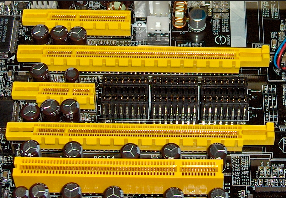
PCIe Bus
The PCI is a platform-independent bus that is connected to the system using a bridge chip (which is part of the motherboard chipset). Whenever a new CPU is released, you can still use the same PCI bus by redesigning the bridge chip instead of redesigning the bus, which was the norm before the PCI bus was created.
A bus is a data path where you can attach several devices at the same time, sharing this data path. The most obvious devices attached to the PCI bus were expansion slots, but integrated components available on the motherboard such as an on-board network chip could be connected to the PCI bus.
Even though other configurations were theoretically possible, the most common implementation of the PCI bus was with a clock with 33 MHz with a 32-bit data path, enabling a bandwidth of 133 MB/s.
Reduce PCIe Bus Latency
The latency values can be read easily with the 'lspci -v' command, and set easily with the 'setpci' command. These commands are present on most Linux installations. The syntax for setting the value is:
setpci -v -s xx:yy.z latency_timer=[n]
Where xx:yy.z are the first numbers listed by lspci, and n is a hex value between 0 and ff (setpci will round down ff, which is actually 255, to the required 248).
Remember that these changes will not persist across a re-boot, and you will probably want to put the setpci commands in a script that runs at boot time, unless your BIOS permits you to set them outside of the OS.
Summary
The initial latency values are set by the system BIOS, and most manufacturers, being lazy, simply set them all to some default, usually 32 or 64, relying on the individual driver routines, such as graphics drivers, to reset the value to something appropriate for that device. This makes sense in a way, as the manufacturer can't know ahead of time what devices might be present on the bus at particular locations (although they *should* be able to figure out that a hard drive probably needs to handle more data than a mouse).


