


- Related articles
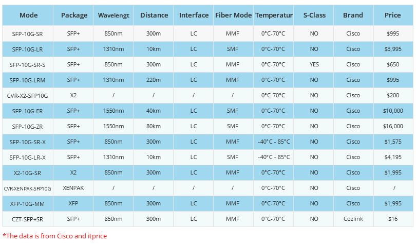
- All Cisco XENPAK-10GB-ZR's information (List price, Specs, Datasheet PDF, Compatibility ma
- Difference between transponder and muxponder
- All Cisco GLC-EX-SMD's information (List price, Specs, Datasheet PDF, Compatibility matrix
- Applicable to 40GBASE-CSR4 Standard Optical Transceiver Models
- All Cisco SFP-OC3-LR1's information (List price, Specs, Datasheet PDF, Compatibility matri
- The difference between CSFP and SFP
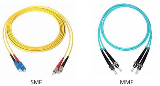
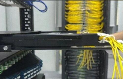
- Naming of Fiber Optic Cable
- All Cisco SFP-10G-BXD-I’s Information (Overview, Features, Data Sheet PDF, Price, Specifi
- What Is the Importance of Network Interface Card?
- What Does LC Stand for in Fiber?


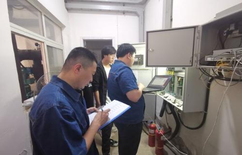
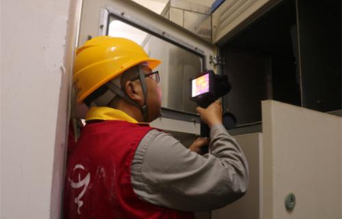
Why Fiber Optic Transceiver Testing is Important?
-
Identify faults and failures:Transceiver testing helps in identifying any faults or failures in the device. The transceiver comprises several components such as a transmitter, receiver, amplifiers, filters, and signal processors. A fault in any of these components can lead to a breakdown in communication. Through transceiver testing, technicians can identify any faults or failures and take corrective action before the issue becomes critical.
-
Optimize performance:Transceiver testing helps in optimizing the performance of the device. By testing the transceiver, technicians can ensure that the device is operating at its maximum capacity. They can adjust the settings of the transceiver to improve the quality of the connection, reduce the noise, and increase the data transfer rate. This optimization results in a better overall user experience.
-
Ensure compliance with standards:Transceiver testing ensures compliance with industry standards. There are specific regulations and standards that govern the use of transceivers in different applications. By testing the transceiver, technicians can ensure that the device complies with these standards. Compliance with these standards ensures that the device is safe, reliable, and performs as expected.
-
Enhance reliability:Transceiver testing enhances the reliability of the device. Reliability is critical for any communication device, and transceivers are no exception. By testing the transceiver, technicians can ensure that the device is reliable and performs consistently. A reliable transceiver ensures that the communication is uninterrupted and consistent, resulting in a better user experience.
-
Reduce downtime:Transceiver testing helps in reducing downtime. An unavailability or a malfunctioning device is described as downtime. Downtime can result in lost productivity, lost revenue, and frustration among users. By testing the transceiver, technicians can identify any potential issues and take corrective action before they result in downtime. This proactive approach helps in reducing downtime and ensuring smooth communication.
-
Minimize costs:Transceiver testing helps in minimizing costs. A faulty or unreliable transceiver can result in additional costs such as repair, replacement, or lost productivity. By testing the transceiver, technicians can identify any potential issues and take corrective action before they become critical. This proactive approach helps in minimizing costs associated with downtime, repair, or replacement.
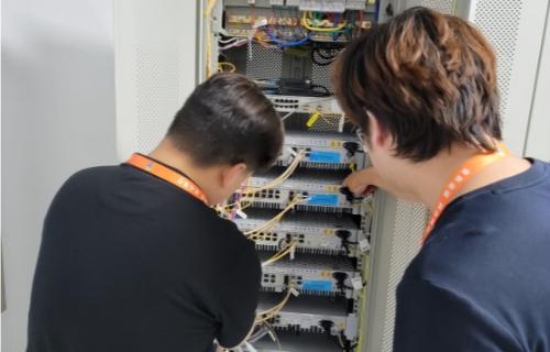
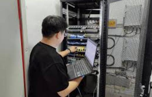
Optical transceivers are an integral part of fiber optic networks. Owing to the growing demand and quality requirements of the optical transceivers, most times manufacturers and suppliers ensure that each individual device has been tested properly. Thus, testing their performance is important. Fiber optics is a multi-parameter technology, so several factors must be considered while testing the optical transceivers. This is why multiple tests are performed by industry experts to inspect and analyze the quality and performance efficiency of optical transceivers. This post discusses different parameters and introduces testing methods of fiber optic transceivers. An optical transceiverfeatures a transmitter and a receiver, so it is important to test this equipment for individual functionality.
When optical transceiver was first deployed, verifying the performance of it was straightforward. The entire network was installed and owned by a single company, and if the system worked, extensive testing of the subcomponents was unnecessary. Today, however, most optical networks use components that may come from a variety of suppliers. Therefore, to test the compatibility and interoperability of each fiber optic transceiver becomes particularly important. How to test a fiber optic transceiver? This article may give you the answer.

As we all know, basically, a fiber optical transceiver consists of a transmitter and a receiver. When a transmitter through a fiber to connect with a receiver but the system doesn’t achieve your desired bit-error-ratio (BER), is the transmitter at fault? Or, is it the receiver? Perhaps both are faulty. A low-quality transmitter can compensate for by a low-quality receiver (and vice versa). Thus, specifications should guarantee that any receiver will interoperate with a worst-case transmitter, and any transmitter will provide a signal with sufficient quality such that it will interoperate with a worst-case receiver.
Precisely defining worst case is often a complicated task. If a receiver needs a minimum level of power to achieve the system BER target, then that level will dictate the minimum allowed output power of the transmitter. If the receiver can only tolerate a certain level of jitter, this will be used to define the maximum acceptable jitter from the transmitter. In general, there are four basic steps in testing an optical transceiver, as shown in the following picture, which mainly includes the transmitter testing and receiver testing.

Transmitter Testing


Receiver Testing


- A mask test, which ensures a large enough eye opening. The mask test is usually accompanied by a BER (bit error ratio) depth.Receiver Testing
- Jitter budget test, which tests for the amount of certain types of jitter.
- Jitter tracking and tolerance, which tests the ability of the internal clock recovery circuit to track jitter within its loop bandwidth.
Stress Testing
Fiber Optic Qualification Test Systems
- 8800 Family of Fiber Optic Test Links
- 802.3ae Qualification Test Link
- LRM / 802.3aq Qualification Test Link
Transceiver Troubleshooting : Top 10 Common Issues & Solutions.
In this article, we'll explore The Top 10 Common Transceiver Issues And Solutionsthat buyers must need to be aware of.
By understanding these issues and taking proactive measures to maintain your transceivers, you can minimize downtime and keep your business running smoothly.
Let’s check out more in details:
-
No signal transmission: If you're not able to transmit signals, the issue could be with the transceiver or with the fiber optic cables. Check that the cables are properly connected, and that the transceiver is properly seated in the port. If the issue persists, you may need to replace the transceiver.
-
No signal reception:If you're not able to receive signals, the issue could be with the transceiver, the fiber optic cables, or the sender device. Check that the cables are properly connected, and that the transceiver is properly seated in the port. If the issue persists, you may need to replace the transceiver.
-
Compatibility issues: Different transceivers are designed to work with different devices and network configurations. If you're experiencing compatibility issues, check that the transceiver is compatible with your device and configuration.
-
Incorrect wavelength: Transceivers are designed to transmit and receive signals at specific wavelengths. If you're experiencing issues with signal transmission or reception, check that the transceiver is using the correct wavelength for your network.
-
Dirty connectors: Dirt, dust, and other debris can accumulate on the connectors of transceivers, causing issues with signal transmission and reception. Clean the connectors with a lint-free cloth and alcohol to remove any debris.
-
Overheating: Transceivers can overheat if they are operating at high temperatures or if they are placed in a poorly ventilated area. Ensure that the transceiver is operating within the recommended temperature range, and that it is properly ventilated.
-
Electrical interference: Electrical interference can cause issues with signal transmission and reception. Ensure that the transceiver is shielded from electrical interference, and that it is properly grounded.
-
Outdated firmware: Outdated firmware can cause issues with signal transmission and reception, and can also impact the compatibility of the transceiver with other devices on the network. Ensure that the firmware is updated regularly to ensure optimal performance.
-
Power issues: Transceivers require a specific amount of power to operate properly. Ensure that the transceiver is receiving the correct amount of power, and that there are no issues with the power supply.
-
Physical damage: Physical damage to the transceiver, such as cracks or bent pins, can cause issues with signal transmission and reception. Inspect the transceiver regularly for any signs of physical damage, and replace it if necessary.
In conclusion, it's important to be aware of the common transceiverissues that can occur and their solutions. By taking proactive measures and regularly maintaining your transceivers, you can minimize downtime and ensure that your business operates smoothly.
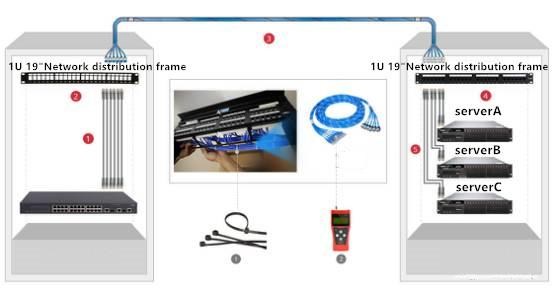
How to determine whether the SFP or Cable is faulty on a Brocade switch
-
How to determine SFP or cable faulty, review the
porterrshowoutput from the switch.-
enc outerrors alone imply primarily a cable issue. -
enc outandcrc errin combination primarily imply a GBIC/SFP problem. -
disc c3combined withc3 timeout txsuggest SFP faulty.
-