- Related articles
- Optical Transceivers for Cisco WS-C3650-48FD-L Switch
- What Is Network Card PCI Express x1?
- Optical Transceivers for Cisco SG350XG-48T-K9-EU Switch
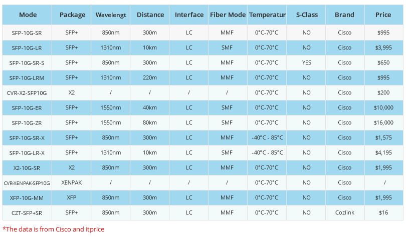
- Serval Cisco Fiber Optic Transceivers
- Optical Transceivers for Cisco WS-C3650-48PD-E Switch
- All Cisco GLC-FE-100FX-RGD's information (List price, Specs, Datasheet PDF, Compatibility
- Cisco Optical Module Decryption Method
- Optical Transceivers for Cisco WS-C2960+24LC-S Switch
- EoS and EoL News for the Cisco 10GBASE DWDM XENPAK Modules
- What is 10GBASE-T transceiver?


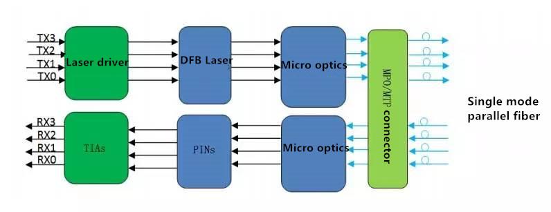
The working principle of optical modules
Optical modules, as an important component of fiber optic communication, are optoelectronic devices that achieve the functions of photoelectric conversion and electro-optic conversion in the process of optical signal transmission. The optical module operates at the physical layer of the OSI model and is one of the core components in fiber optic communication systems. It mainly consists of optoelectronic devices (optical emitters, optical receivers), functional circuits, and optical interfaces, and its main function is to achieve photoelectric conversion and electro-optical conversion functions in fiber optic communication. The working principle of the optical module is shown in the schematic diagram of the optical module.
The optical module may encounter some common problems during use, and the following are some common optical module faults:
The optical module port is contaminated: The optical module port may be blocked by foreign objects, such as dust or other pollutants, causing the optical module to not function properly. This is usually due to fiber optic jumpers not being used for a long time and without protective measures, the joints are covered in dust, and the ports are contaminated when inserting optical modules.
The optical module is not tightly inserted or unplugged improperly: If the optical module is not tightly inserted or the operation during the unplugging process is not standardized, it may lead to limited optical signal transmission and even cause the fiber optic jumper to break inside the optical module, thereby damaging the optical module.
Using non-standard or inferior fiber optic connectors or jumpers: These non-standard or inferior components may damage the optical module during use, affecting its normal function.
The conductive metal of the gold finger of the optical module is damaged: If the conductive metal of the gold finger of the optical module is damaged or missing, it may cause the optical module to be unusable.
Incompatible optical modules: Different manufacturers and models of optical modules may have compatibility issues. If the optical module is incompatible with the device or system, it may cause communication failures, performance degradation, or malfunction. Therefore, when selecting optical modules, it is necessary to ensure their compatibility with devices and systems.
Performance degradation of optical modules: The performance of optical modules may gradually decrease with increasing usage time, such as decreased optical power and decreased reception sensitivity. This may be caused by aging, contamination, or damage to the internal components of the optical module. A decrease in performance may affect the transmission distance and stability of the optical module, requiring regular inspection and replacement of the optical module.
Overheating of the optical module: The optical module generates a certain amount of heat during operation. If the heat dissipation is poor or the working environment temperature is too high, it may cause the optical module to overheat. Overheating may affect the performance and stability of the optical module, and even damage the optical module. Therefore, it is necessary to ensure that the working environment temperature of the optical module is suitable and take effective heat dissipation measures.
Damaged optical module ports: The ports of the optical module may be damaged due to improper plugging, external impact, or contamination. Port damage may cause limited or complete interruption of optical signal transmission, and it is necessary to replace the optical module or repair the port in a timely manner.
The fault indicator light of the optical module is on:The optical module is usually equipped with a fault indicator light to indicate the working status of the optical module. If the fault indicator light is on, it indicates that there is a fault or abnormality in the optical module. At this point, it is necessary to check the connection, power supply, configuration, and other aspects of the optical module to determine the cause of the fault and take corresponding measures.
What are the key performance indicators of optical modules
How to measure the performance indicators of optical modules? We can understand the performance indicators of optical modules from the following aspects.
Center wavelength: refers to the optical band used for optical signal transmission and is an important parameter of the optical module. The wavelength of the optical module determines the frequency range of the transmitted optical signal, and different wavelengths correspond to different transmission characteristics and application scenarios.
Emission optical power: The optical power output by the transmitting end of the optical module during operation is called the emission optical power. It measures the ability of an optical module to send optical signals, usually expressed in dBm. The magnitude of the emitted light power directly affects the transmission distance and signal quality of the optical module.
Receiving sensitivity: The minimum optical power that can be detected by the receiving end of an optical module, which is also an important indicator of the performance of the optical module. The higher the receiving sensitivity, the better the performance of the optical module in receiving weak light signals.
Extinction ratio: refers to the ratio of the average output optical power of a laser when emitting all "1" to the average output optical power when emitting all "0". The size of the extinction ratio affects the signal quality and error rate of the optical module.
Optical Signal to Noise Ratio (OSNR): measures the proportion of noise in an optical signal. The higher the OSNR, the better the quality of the optical signal and the more stable the transmission performance.
Dispersion and loss:Dispersion refers to the signal distortion caused by the different propagation speeds of light waves of different frequencies in the medium during the transmission of optical signals; Loss refers to the decrease in signal strength caused by absorption and scattering of optical fibers during the transmission of optical signals. Both of these factors will affect the transmission performance of the optical module.
Transmission distance: The maximum distance that an optical module can stably transmit optical signals, which is influenced by a combination of factors such as emitted light power, received sensitivity, dispersion, and loss.
Working temperature range: The temperature range within which the optical module operates normally. Exceeding this range may cause a decrease in the performance or damage of the optical module.
Bandwidth:refers to the frequency range of optical signals that an optical module can process. The wider the bandwidth, the higher the data transmission rate that the optical module can support.
Interface compatibility: The optical module needs to be connected to other devices in the optical communication system (such as switches, routers, etc.), so its interface must be compatible with the interfaces of these devices. Common interface types include SFP, SFP+, XFP, etc.
Reliability: The stability of optical modules in long-term operation and harsh environments, as well as their ability to continuously provide high-quality transmission performance.
Size: The size of the optical module needs to adapt to the slots and design of the optical communication equipment, especially in environments with limited space, selecting the appropriate size of the optical module is particularly important.
Packaging type: The packaging method of the optical module, such as metal packaging, plastic packaging, etc. The packaging type will affect the heat dissipation performance, mechanical strength, and cost of the optical module.
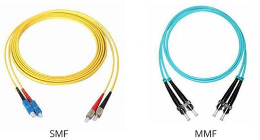
Polarization mode: For certain special applications, such as high-speed optical communication or long-distance transmission, the polarization mode of the optical module (such as single-mode or multi-mode) is also an important consideration factor.
Hot swapping function: Does the optical module support hot swapping, which means that when the device is powered on, it can be safely inserted or removed without affecting the normal operation of other parts. This feature is very useful for maintaining and upgrading optical communication systems.
Power supply voltage: The range of power supply voltage required for the normal operation of the optical module. Different models of optical modules may have different power supply requirements, and it is necessary to ensure that appropriate power supply is provided to ensure their normal operation.
Electromagnetic compatibility (EMC): The anti-interference ability of optical modules in electromagnetic environments and the electromagnetic radiation impact on other devices. Good electromagnetic compatibility helps to ensure the stability and reliability of optical modules in complex electromagnetic environments.
Digital diagnosis function: Some advanced optical modules have digital diagnosis function, which can monitor the working status of the optical module in real time and provide feedback information on key parameters, such as temperature, voltage, optical power, etc. This helps to detect optical module faults in a timely manner and take corresponding measures.
Eye image quality:Eye images are a graphical representation used to evaluate the quality of digital signals, which can reflect the noise, jitter, and distortion of the signal. The quality of the eye diagram of the optical module directly affects the transmission quality and error rate of the signal.
Long term stability: The performance stability of optical modules during long-term operation, including the stability of optical power and changes in receiving sensitivity. Long term stable optical modules can ensure the continuous and stable operation of optical communication systems.
Cost effectiveness: When considering the performance indicators of optical modules, it is also necessary to comprehensively consider their cost-effectiveness. Choosing cost-effective optical modules can help reduce overall costs while meeting system requirements.
What should be done if the optical module malfunctions
When the optical module malfunctions, the following steps can be taken to handle it:
Preliminary fault diagnosis: Firstly, by observing the status indicator lights or system prompts of the light module, the type of fault can be preliminarily determined. Common types of faults include low optical power, no optical output, and port damage.
Appearance inspection: Conduct an appearance inspection of the optical module to check for obvious physical damage, such as port contamination, component detachment, etc. If physical damage is found, the optical module needs to be replaced in a timely manner.
Optical power and signal quality testing: Use an optical power meter and signal quality testing instrument to test the output optical power and signal quality of the optical module. If the optical power is too low or the signal quality is poor, it may be due to aging or damage of the internal components of the optical module, and the optical module needs to be replaced.
Compatibility check: Confirm the compatibility of the optical module with the device and system. If the optical module is incompatible with the device or system, it may cause communication failures or performance degradation. At this point, it is necessary to replace the optical module that is compatible with the device and system.
Contact the supplier or technical support: If the above steps cannot solve the problem, it is recommended to contact the optical module supplier or technical support team for professional troubleshooting and solutions.
Comprehensive performance indicators
Interface speed
The maximum error free transmission rate of electrical signals that optical devices can carry, as specified by Ethernet standards, includes 125Mbit/s, 1.25Gbit/s, 10.3125Gbit/s, and 41.25Gbit/s.
transmission distance
The distance that optical modules can transmit is mainly limited by both loss and dispersion. Loss refers to the loss of optical energy caused by the absorption, scattering, and leakage of the medium during the transmission of light in optical fibers. This energy is dissipated at a certain ratio as the transmission distance increases. The generation of dispersion is mainly due to the unequal propagation speed of electromagnetic waves of different wavelengths in the same medium, resulting in different wavelength components of optical signals reaching the receiving end at different times due to the accumulation of transmission distance, leading to pulse broadening and inability to distinguish signal values.
In terms of dispersion limitation in optical modules, the limited distance is much greater than the limited distance of loss, so it can be disregarded. The loss limit can be estimated based on the formula: loss limited distance=(emitted light power - received sensitivity)/fiber attenuation. The attenuation of optical fibers is strongly correlated with the actual selected optical fibers.