Split 1 input signal evenly into 2 output ports
Low Insertion Loss ≤3.8dB without connectors /4.1dB with connectors
Low PDL (Polarization Dependent Loss) ≤0.2dB
Compact Design
Fully Passive Optical Branching Device
Wide Operating Wavelength: 1260nm to 1650nm
G.657A1 Bend Insensitive Fibers for Low Bending Loss
Wide Operating Temperature: -20°C to 70°C
Conformed to RoHS
FTTX Systems
LAN, WAN and Metro Networks
Analog/Digital Passive Optical Networks
CATV Networks
Other Applications in Fiber Optic Systems

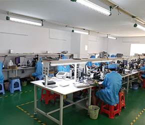
OEM Manufacturer
SEESUO provides tailored OEM products based on clients' designs and specs.

ODM Manufacturer
SEESUO boastis rich R&D experence and top-notch production management.

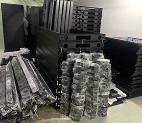
Customized production
SEESUO provides talored product design,development, and flexible manufacturing.

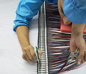
R&D cooperation
SEESUO adapts swifly to market changes collaborating with customers in R&D.
-
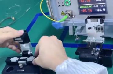 Mechanical Durability InspectiAssesses physical durability of splitter components to withstand handling, installation, and long-term use without performance degradation.
 -
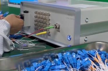 Environmental Stability AnalysTests performance under varying temperatures and humidity to ensure stable operation in diverse environmental conditions.
 -
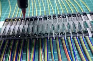 Wavelength Range ValidationVerifies splitter performance across specified wavelength ranges to confirm compatibility with different wavelengths in fiber networks.
 -
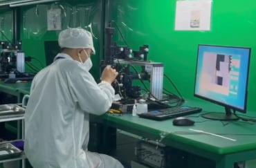 Return Loss EvaluationEvaluates reflection loss within the splitter, ensuring high return loss values to prevent signal disruption and enhance stability.
 -
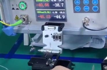 Uniformity AssessmentAssesses signal uniformity across output channels to guarantee even power distribution, vital for consistent network performance.
 -
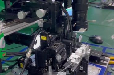 Optical Insertion Loss MeasureMeasures insertion loss across splitter outputs to confirm minimal signal attenuation, ensuring efficient signal distribution.
What causes attenuation in optical fiber?
How to measure attenuation in optical fiber
How to connect fiber patch panel to switch
5.0

 دينا زكرياDina ZakariaEgypt
 5.0This 1x2 steel tube splitter is perfect for my small FTTH setup with a Huawei OLT. The SC/APC connectors deliver strong signals, and the 0.35m length is ideal for tight spaces.
 Mark EvangelistaPhilippines
 4.9Great product for my Cisco switch! The 250μm fiber design makes it super compact, and the signal quality with the SC/APC connectors is spot on.












 Online consultation
 Send email


